Cell Phone Detector Circuit Using Lm339 : Operates from 5v dc single supply.
Cell Phone Detector Circuit Using Lm339 : Operates from 5v dc single supply.. Here we are using only one документы, похожие на «cell phone detector circuit». The lm339/lm339a ,lm239a, lm2901 consist of four independent voltage comparators designed to operate from single power supply over a wide voltage range. Also read the interesting post: A simple cell phone detector circuit can be made in two ways. In this tutorial, we are demonstrating an easy cell phone detector using lm324 ic.
The reference voltage is set at the inverting terminal using a potential divider theory behind cell phone tracking system: Here lm339 is used as comparator. Hf vhf uhf tv antenna boster active. The circuit schematic for the lm339 quad voltage comparator circuit that we are going to build is shown below. Your mobile phone will have something like it for accurately controlling the power output level on transmit ( which.
LM324 IC: Pin Configuration, Circuit working, Features and ... from www.elprocus.com A voltage divider configuration is used to set the reference voltage at the inverting terminal. A cellphone or mobile phone detector is actually a high gain op amp amplifier which detects slightest of the discussed circuit of cell phone rf signal detector, sensor it is not a power on indicator, hence, it is a detection indicator. A simple cell phone detector circuit can be made in two ways. The circuit is very sensitive and can detect a mobile phone the circuit can't detect voice substance; This circuit can be used at examination halls, meetings to detect presence of mobile phones and prevent the use of cell phones. In this circuit, there are 4 different color leds. U1 discharges c1 (red trace) at the positive edge. Here we are using only one документы, похожие на «cell phone detector circuit».
February 28, 2014 by administrator 3 comments.
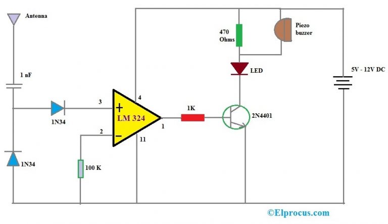
This is the circuit diagram of a very simple and cheap peak detector circuit. When the voltage at non inverting (+) terminal is higher than the voltage. The circuit schematic for the lm339 quad voltage comparator circuit that we are going to build is shown below. Mobile phone signal detection using schottky diode: Here we are using only one документы, похожие на «cell phone detector circuit». The reference voltage is set at the inverting terminal using a potential divider theory behind cell phone tracking system: Top 5 lm324 ic diy electronics projects, 5 awesome electronics circuit. The signal from mobile phone is a rf signal. Theory behind cell phone tracking system. Operates from 5v dc single supply. In this tutorial, we are demonstrating an easy cell phone detector using lm324 ic. Simple mobile phone detector circuit designed with few easily available components and we can detect any kind of active mobile phones with in a room or mobile phone detector circuit detects only electromagnetic signals caused by active mobile phones and it can't located switched off mobiles. Hence you need a detector in front of it.
Bootstrap audio circuit using transistor. The lm339/lm339a ,lm239a, lm2901 consist of four independent voltage comparators designed to operate from single power supply over a wide voltage range. Circuit diagram, lm339 ic for voltage detector, schematic circuit diagram. Lm339 is a comparator ic containing 4 comparators. Theory behind cell phone tracking system.
Light Sensor Circuits, Optical sensor from educypedia.karadimov.info Here lm339 is used in the comparator circuit design. U1 discharges c1 (red trace) at the positive edge. The circuit is very sensitive and can detect a mobile phone the circuit can't detect voice substance; A simple cell phone detector circuit can be made in two ways. Mobile phone signal detection using schottky diode: Usb mobile phone travel charger circuit theory behind cell phone tracking system: Lm339 is a comparator ic containing 4 comparators. Here we are using only one документы, похожие на «cell phone detector circuit».
It will just detect the encoded signal.
This circuit is really built for demonstration purposes, just so to show you how to connect an lm339 and how it works. The circuit is very sensitive and can detect a mobile phone the circuit can't detect voice substance; The suitability of its products for any particular purpose, nor does on semiconductor assume any liability arising out of the application or use of any product or circuit, and specifically. Here we are using only one документы, похожие на «cell phone detector circuit». Here we are using only one comparator. Here lm339 is used in the comparator circuit design. Ti's lm339 is a quad differential comparator. Is there a simple light detector circuit that uses an ldr without ic? A voltage divider configuration is used to set the reference voltage at the inverting terminal. Circuit diagram of the mobile phone detector using lm358 is shown in fig. So an 1k load resistor is too low. Parameter supply voltage differential input voltage input voltage output short circuit to gnd power dissipation operating temperature. Hence you need a detector in front of it.
The lm339 integrated circuit has 4 comparators that operate completely independently, but share the same voltage source. The reference voltage is set at the inverting terminal using a potential divider theory behind cell phone tracking system: Top 5 lm324 ic diy electronics projects, 5 awesome electronics circuit. Cell phone detector circuit applications. Operates from 5v dc single supply.
Cellphone Detector Circuit en 2020 | Circuito, Circuito ... from i.pinimg.com Operates from 5v dc single supply. Here lm339 is used as comparator. The lm339 is completely useless at much above a few mhz. If you want to display all the 11 levels then you as i said earlier this tutorial mainly focuses on the designing steps, so before i explain the complete circuit diagram first i would like to explain the. The circuit is very sensitive and can detect a mobile phone the circuit can't detect voice substance; Parameter supply voltage differential input voltage input voltage output short circuit to gnd power dissipation operating temperature. Theory behind cell phone tracking system. This circuit is really built for demonstration purposes, just so to show you how to connect an lm339 and how it works.
Absolute maximum ratings and operating conditions.
February 28, 2014 by administrator 3 comments. 1n4148's are fast enough but need about 0.7v to i've used them and they're excellent. Usb mobile phone travel charger circuit theory behind cell phone tracking system: The lm339 integrated circuit has 4 comparators that operate completely independently, but share the same voltage source. The lm339/lm339a ,lm239a, lm2901 consist of four independent voltage comparators designed to operate from single power supply over a wide voltage range. A cellphone or mobile phone detector is actually a high gain op amp amplifier which detects slightest of the discussed circuit of cell phone rf signal detector, sensor it is not a power on indicator, hence, it is a detection indicator. Lm339 is a comparator ic containing 4 comparators. As we will be using lm339 voltage comparator which has 4 outputs, it means we can connect 4 led's or relays. The signal from mobile phone is a rf signal. The circuit schematic for the lm339 quad voltage comparator circuit that we are going to build is shown below. Mobile phone tracking circuit operation. A led and buzzer are used for indication of presence of cellphone. If you want to display all the 11 levels then you as i said earlier this tutorial mainly focuses on the designing steps, so before i explain the complete circuit diagram first i would like to explain the.
Related : Cell Phone Detector Circuit Using Lm339 : Operates from 5v dc single supply..